Flashing to the OBC
The following is a simple guide for flashing to the OBC.
There are two main ways to flash to the OBC: using the bootloader or using UniFlash. UniFlash is the more common way so let’s go over that first.
Flashing via UniFlash
Section titled “Flashing via UniFlash”-
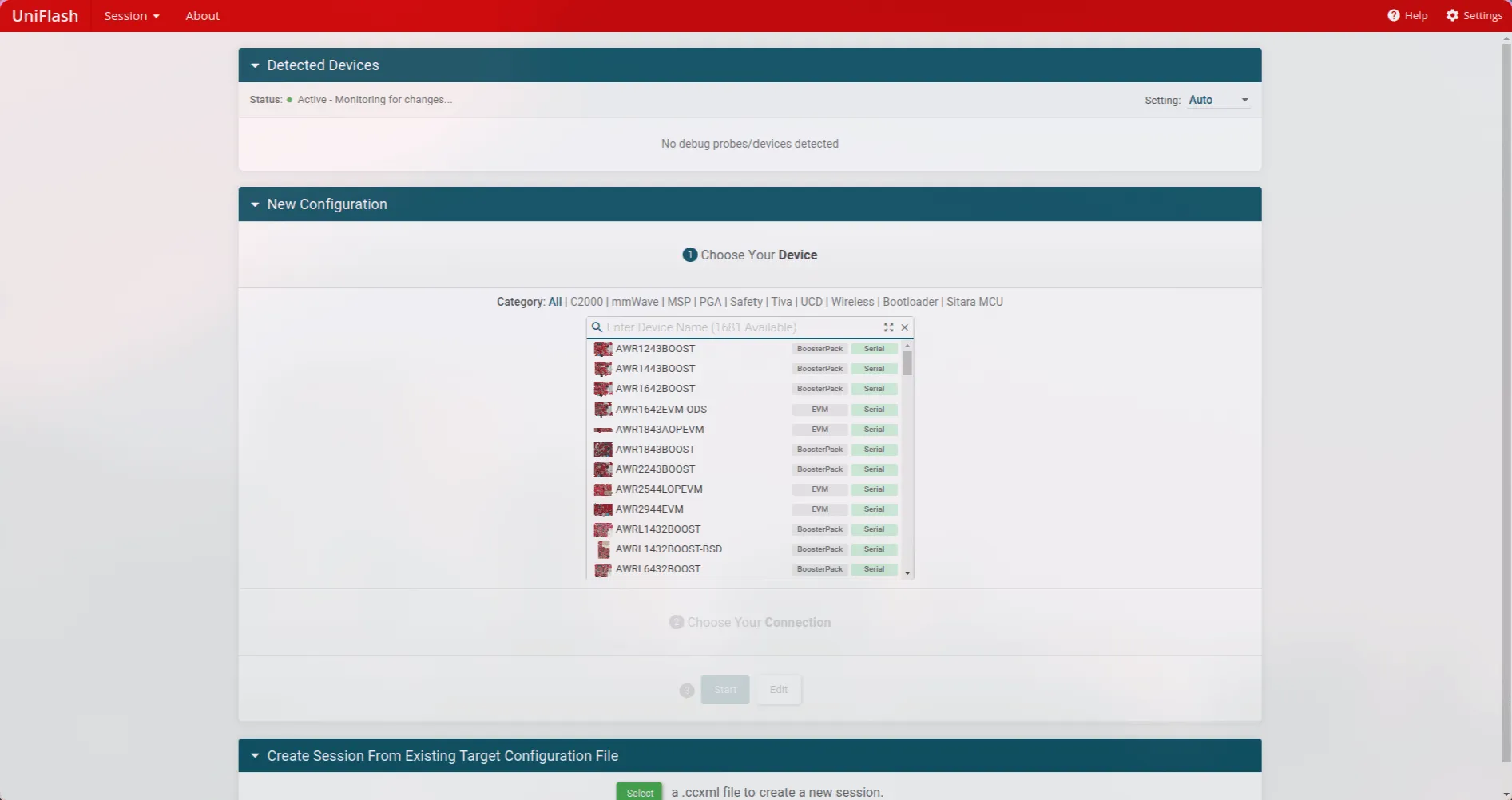
When you open UniFlash you should be greeted with the following screen…
-
For the chip select
RM46L852if you are using OBC Revision 1 or OBC Revision 2. If you are using the Launchpad, selectLAUNCHXL2-RM46. -
Then for the connection, choose
Texas Instruments XDS110 USB Debug Probe -
Now press
Startand you should see the following screen.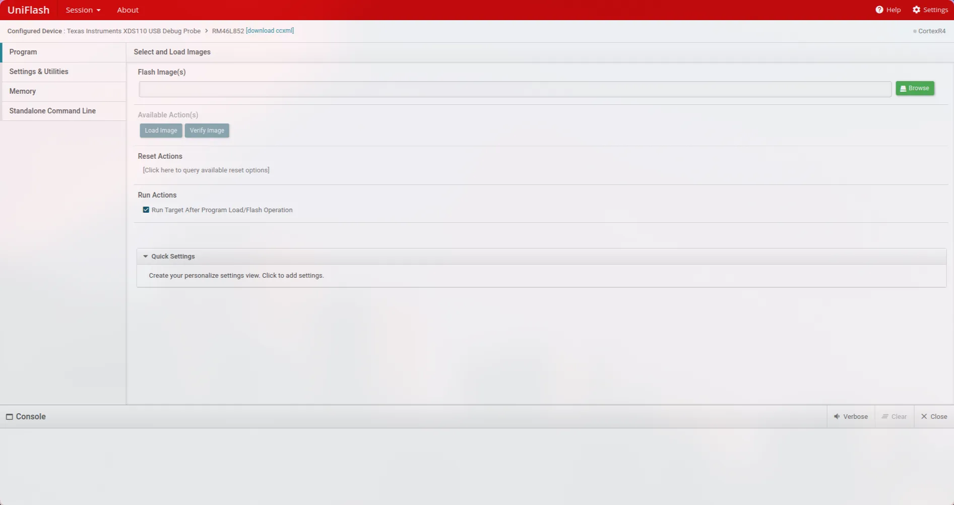
-
Browse for the file with a
.outsuffix that you would like to flash and then pressLoad Image. Usually you will flash one of the following files…OBC-firmware.outin thebuild_armdirectory >> This contains the main app to run on the OBC.OBC-bl.outin thebuild_armdirectory >> This contains the bootloader for the OBC.- An OBC example file from the
build_examplesdirectory >> This is for when you want to test specific functionality on the OBC (assuming you have written a test file for it and added it to the build script; see Building examples).
Accessing UART
Section titled “Accessing UART”This is an important skill everyone should know just for debugging. We will go through the process for Windows and Linux.
Base setup
Section titled “Base setup”Both Linux and Windows have a program called puTTY available to download. puTTY is a great program to detect serial activity on ports so make sure you download this before proceeding!
-
Download and open
puTTY. You should be greeted with the following screen…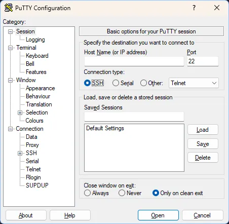
-
Under the
Connection Type:section, select theSerialoption which should makepuTTYshow the following.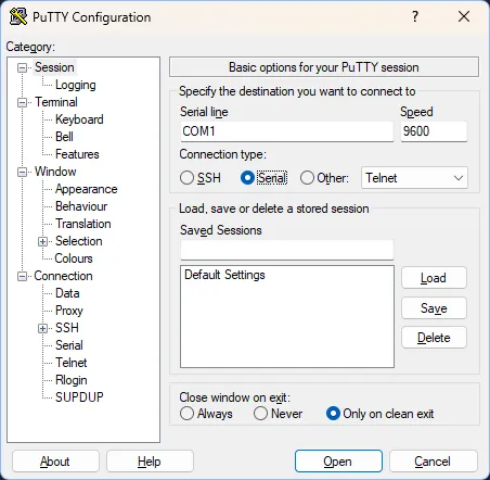
-
You can set the speed to
115200which is the baud rate at the time of writing this tutorial (August, 2025). Update this rate if the baud rate of the board is increased! -
If you know how to detect what USB port is connected to UART you can type that USB port into the
Serial linefield inpuTTY. If you need help, read through the following sections! -
You can then press the
Openbutton and there should be a black screen that starts printing out text sent by the board!
Finding USB port on Linux
Section titled “Finding USB port on Linux”On Linux the port name will be in the form of /dev/tty*. For example the port could be named /dev/ttyACM0 or /dev/ttyUSB0. To find the port connected to the board do the following…
- Open up a terminal without the board connected and type in the following command that will list out all file paths starting with
/dev/ttyTerminal window ls /dev/tty* - Now connect the board and repeat the same command.
- Look for differences in outputs between running the command before and after connecting the board. The
/dev/ttyfile path that gets added the second time around is the port that your board is connected on! - You can type the name of the port you have determined to be going to the board in the
Serial linefield inpuTTY. If you are using JTAG and have to connect two USBs to your Linux system, you will have to experiment and see which port outputs logs on puTTY.
Finding USB port on Windows
Section titled “Finding USB port on Windows”On Windows the port name will be in the form of COMXX with XX denoting numbers. For example possible port names are COM1, COM12, etc. To find the port connected to the board do the following…
- Open
Device Managerand you should be greeted with the following (the image is taken off the web so your window may look a bit different)…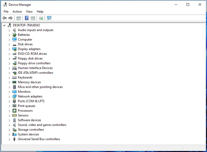
- Under
Portstry to find the COM port labelled withUARTsomewhere in it’s name. Once you have found it that is the COM port you will be using inpuTTY.
Working with USB on WSL (usbipd)
Section titled “Working with USB on WSL (usbipd)”Unfortunately Windows does not pass-through USB ports by default to WSL. Thus, we have to use a utility called usbipd to handle USB device pass-through in WSL. The following are the steps needed to attach/detach USB devices from WSL.
-
Open a
PowerShellwindow. Within the window type the following command to find the bus-id of the USB device that you want to attach.PowerShell usbipd listYou need to locate the device that has UART in it’s name and make note of the busid that will show in the left most column of the command’s output.
-
If the device’s
STATEshows up asshared, you may skip this step else execute the command. The example is using the busid of1-1for demonstration purposesPowerShell usbipd bind --busid 1-1 -
If the device’s
STATEshows up asattached, you may skip this step else execute the command. Again this example uses a busid of1-1for demonstration purposes.PowerShell usbipd attach --wsl --busid 1-1 -
If you ever need to detach the USB port (to use
puTTYfor example) then you can run the following command. Again this example uses a busid of1-1for demonstration purposes.PowerShell usbipd detach --busid 1-1
Flashing via the bootloader
Section titled “Flashing via the bootloader”-
Use UniFlash to flash the
OBC-bl.outfile, ensuring you have built it for the correct board using the right argument for the-DBOARD_TYPE=option. -
From the root directory activate the python virtual environment with the following command
Terminal window source venv/bin/activate -
Navigate to the
obc/tools/python/directory from root…Terminal window cd obc/tools/python/ -
Run the app
app_update.pyscript specifying a USB port and the absolute file path. The following are some examples.Terminal window # On Linux and WSLpython3 app_update.py /dev/ttyS0 ~/OBC-firmware/build_arm/OBC-firmware.bin# On Linux and WSLpython3 app_update.py /dev/ttyUSB0 ~/OBC-firmware/build_arm/OBC-firmware.bin -
Wait for the script to flash and the board should jump to app within 2 seconds of when flashing is completed. If not check the error that is being logged to UART and try again!